Nuggets
Member
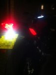
I was recently asked by a forum member how I installed the red EL panels to my MT07 (pic below)
This is what I did;
I purchased the EL panel EL craft.
Large EL Panel- 15cm X 40cm with 4 Connectors | EL Wire Craft
I cut both sides from one panel, making sure each cut out has a connector!
I also purchased a splitter cable - you could solder connections but for the cost I did bought the splitter so that if I had to breakdown the bike for any reason (to get out battery .etc) then all I have to do is disconnect the wiring to the panels.
2 to 1 Splitter for EL Tron Wire | EL Wire Craft
I also then used a small 12v driver/inverter. EL panel is different to LED lighting that it is more difficult to size the driver so I went for a small package 12V waterproof EL unit and hoped it would work. The driver is fixed voltage and frequency and its not as flexible as LED (i.e. you can't dim or make it flash or pulse easily).
Tiny Water Resistant 12V Inverter for up to 5 meters EL Wire | EL Wire Craft
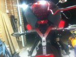
The EL panel's were then squeezed between the existing plastic bodywork and the aftermarket mesh covers. A word of warning if you try and curve the EL panel to match the bodywork the EL material may start to delaminate especially if they are bent too much, don't heat the panel to try and bend them either that doesn't work!
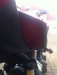
In the end I sandwiched them between the plastic body work and the aftermarket mesh covers flat with no curves, it took a bit of patience and some brute force to get the mesh fixed despite the panels being thin (1-2mm thick) and flexible there just isn't that much tolerance.
When cutting the panel it is recommended the cut edge with nail varnish or superglue, this prevents the panel from delaminating. I used superglue.
The rest is plug and play - 12v driver plugs to splitter cable which plugs to each panel.
before re-assembly a quick test off a 12v supply ensures it's all working.
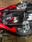
To power the driver I cut off the lighter socket plug and used the feed to the tail light / brake light.
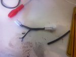
I didn't want to cut into the bike's wiring to take off the power. There is a white waterproof three pin plug under the passenger seat cowel.

I got another one of these white connectors off the internet and made up a short loom (straight through with two spliced connections for the ground and the tail light supply cut into the cable :- the black & blue wires from the original wiring)
3 Way (Tri) White Speed Gear Sensor Wiring Loom Connector
The white plug is too small to take two cables straight off the pins so I spliced a couple of wires half way down the loom and then nicked a hole in heat shrink and thread it over the two sets of wires before putting the terminating.
In the future if I want to remove the install then it's simply a case of unplugging and returning to stock.
You don't have to do the last step but I thought it was easier than cutting into the existing wiring loom and soldering connections.
if you want the EL panels to come on with the brake light then you should switch the blue cable for the yellow cable from the original loom.
IMO the EL panel isn't bright enough to be used effectively as an additional brake light but it's entirely possible to use it as such, there is no fade or delay from the inverter so the EL panel will switch on and off at the same rate (pretty much) as the brake light.
EL wire is also available and works on the same principle for those of you wanting to live out your TRON fantasy!
This is what I did;
I purchased the EL panel EL craft.
Large EL Panel- 15cm X 40cm with 4 Connectors | EL Wire Craft
I cut both sides from one panel, making sure each cut out has a connector!
I also purchased a splitter cable - you could solder connections but for the cost I did bought the splitter so that if I had to breakdown the bike for any reason (to get out battery .etc) then all I have to do is disconnect the wiring to the panels.
2 to 1 Splitter for EL Tron Wire | EL Wire Craft
I also then used a small 12v driver/inverter. EL panel is different to LED lighting that it is more difficult to size the driver so I went for a small package 12V waterproof EL unit and hoped it would work. The driver is fixed voltage and frequency and its not as flexible as LED (i.e. you can't dim or make it flash or pulse easily).
Tiny Water Resistant 12V Inverter for up to 5 meters EL Wire | EL Wire Craft
The EL panel's were then squeezed between the existing plastic bodywork and the aftermarket mesh covers. A word of warning if you try and curve the EL panel to match the bodywork the EL material may start to delaminate especially if they are bent too much, don't heat the panel to try and bend them either that doesn't work!
In the end I sandwiched them between the plastic body work and the aftermarket mesh covers flat with no curves, it took a bit of patience and some brute force to get the mesh fixed despite the panels being thin (1-2mm thick) and flexible there just isn't that much tolerance.
When cutting the panel it is recommended the cut edge with nail varnish or superglue, this prevents the panel from delaminating. I used superglue.
The rest is plug and play - 12v driver plugs to splitter cable which plugs to each panel.
before re-assembly a quick test off a 12v supply ensures it's all working.
To power the driver I cut off the lighter socket plug and used the feed to the tail light / brake light.
I didn't want to cut into the bike's wiring to take off the power. There is a white waterproof three pin plug under the passenger seat cowel.
I got another one of these white connectors off the internet and made up a short loom (straight through with two spliced connections for the ground and the tail light supply cut into the cable :- the black & blue wires from the original wiring)
3 Way (Tri) White Speed Gear Sensor Wiring Loom Connector
The white plug is too small to take two cables straight off the pins so I spliced a couple of wires half way down the loom and then nicked a hole in heat shrink and thread it over the two sets of wires before putting the terminating.
In the future if I want to remove the install then it's simply a case of unplugging and returning to stock.
You don't have to do the last step but I thought it was easier than cutting into the existing wiring loom and soldering connections.
if you want the EL panels to come on with the brake light then you should switch the blue cable for the yellow cable from the original loom.
IMO the EL panel isn't bright enough to be used effectively as an additional brake light but it's entirely possible to use it as such, there is no fade or delay from the inverter so the EL panel will switch on and off at the same rate (pretty much) as the brake light.
EL wire is also available and works on the same principle for those of you wanting to live out your TRON fantasy!
