I bought a set of oxford hot grips for the MT and have seen alot of people wiring them (and other makes) straight to the battery. The oxford premium grips do have a battery save function where they switch off if the battery voltage goes low or the detect no "noise" on the electrical supply which suggests the engine is not running.
However I don't trust this function and I've been stranded before with a dead battery and bump starting is not something I'm good at so I wired in a relay into the hot grips power supply to switch off when the ignition is off. It's really easy to do and put together a how to on it here.
First off is to install the grips which is simple and I won't talk about that here as it's just to take off the old grips and put the new hot grips on with the glue supplied ensuring the cables are in the right position and there's no fouling (especially with the throttle grip!)
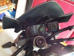
Then fit the controller where you want it to be. I put mine on the screen fixing point as I have no space on the handlebars due to the huge mobile phone mount I've put on (not shown)
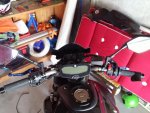
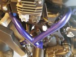
Once in place you can connect the grips to the controller and tidy away cables, I routed mine to behind the left hand fairing behind the regulator/rectifier and cable tied them in place.
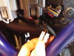
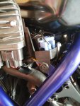
You need to remove rider seat and left hand fairing to access battery and the auxiliary power socket. I struggled to find the aux power socket as it's hidden really well, you need to kneel down and look under the regulator. you'll see a white connector that looks like one part is fixed to the wiring loom. If you pull out the male part you'll see the that 2 wires go into the male part you just pulled out but there's nothing in the female part (no connectors or wires) which is taped into the wiring loom.
Picture below shows after I pulled out the male part
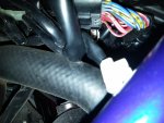
I cut off the male part and connected the two wires into a screwed terminal block (as I didn't have any other spare connectors and it was Sunday so the shops were closed...)
This aux connector has two wires into it a black/white wire which is negative and a red/yellow wire which is positive. This positive is switched by the ignition, so it is only live when ignition is in the ON position. See attached extract of wiring diagram.
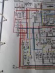
The aux socket is number 88 on the bottom left, follow the red/yellow line up and you'll see it is fed from fuse number 6, which is switched by the ignition item 1 on drawing.
This aux supply will be used to switch the relay on and off with the ignition.
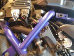
Next I installed the relay on the plastic tray the regulator is connected to, there's space there to bolt it in place. My relay was a 30A standard auto relay as shown below:-
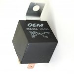
I wired from the aux socket positive to pin 85 on the relay and the aux socket negative to pin 86. so now the relay switches with the ignition. I tested the relay and the coil draws on 0,1A so you can still use the aux socket to power other things (like I have)
The power cable from the hot grips controller need to run to under the rider seat to connect to the battery, but do not connect it yet. The power cable has a negative and a positive wire. The negative does not need to be cut, but you need to identify which wire is the positive and cut that wire.
Then it's just to connect the positive wire ends to pins 30 and 87 on the relay.
Once those connections are made you can connect the power cable to the battery + and - (checking the grips positive is fused! if it does not have a fuse then you MUST fit one as close to the battery as possible)
Tidy up and secure all the wires with cable ties to ensure nothing vibrates loose. Note that although this area of the bike is pretty much sheltered from the elements by the side panels I still used self amalgamating tape on my connector block to be sure to keep water out, the oxford connectors didn't need this and I orientated the relay so the likelihood of water getting on the pins was low. I've been out is all sorts of weather and everything works perfectly.
This will mean that you can never leave the grips on when the bike is off, avoiding that awful moment when you have to try to bump start the bike.
However I don't trust this function and I've been stranded before with a dead battery and bump starting is not something I'm good at so I wired in a relay into the hot grips power supply to switch off when the ignition is off. It's really easy to do and put together a how to on it here.
First off is to install the grips which is simple and I won't talk about that here as it's just to take off the old grips and put the new hot grips on with the glue supplied ensuring the cables are in the right position and there's no fouling (especially with the throttle grip!)
Then fit the controller where you want it to be. I put mine on the screen fixing point as I have no space on the handlebars due to the huge mobile phone mount I've put on (not shown)
Once in place you can connect the grips to the controller and tidy away cables, I routed mine to behind the left hand fairing behind the regulator/rectifier and cable tied them in place.
You need to remove rider seat and left hand fairing to access battery and the auxiliary power socket. I struggled to find the aux power socket as it's hidden really well, you need to kneel down and look under the regulator. you'll see a white connector that looks like one part is fixed to the wiring loom. If you pull out the male part you'll see the that 2 wires go into the male part you just pulled out but there's nothing in the female part (no connectors or wires) which is taped into the wiring loom.
Picture below shows after I pulled out the male part
I cut off the male part and connected the two wires into a screwed terminal block (as I didn't have any other spare connectors and it was Sunday so the shops were closed...)
This aux connector has two wires into it a black/white wire which is negative and a red/yellow wire which is positive. This positive is switched by the ignition, so it is only live when ignition is in the ON position. See attached extract of wiring diagram.
The aux socket is number 88 on the bottom left, follow the red/yellow line up and you'll see it is fed from fuse number 6, which is switched by the ignition item 1 on drawing.
This aux supply will be used to switch the relay on and off with the ignition.
Next I installed the relay on the plastic tray the regulator is connected to, there's space there to bolt it in place. My relay was a 30A standard auto relay as shown below:-
I wired from the aux socket positive to pin 85 on the relay and the aux socket negative to pin 86. so now the relay switches with the ignition. I tested the relay and the coil draws on 0,1A so you can still use the aux socket to power other things (like I have)
The power cable from the hot grips controller need to run to under the rider seat to connect to the battery, but do not connect it yet. The power cable has a negative and a positive wire. The negative does not need to be cut, but you need to identify which wire is the positive and cut that wire.
Then it's just to connect the positive wire ends to pins 30 and 87 on the relay.
Once those connections are made you can connect the power cable to the battery + and - (checking the grips positive is fused! if it does not have a fuse then you MUST fit one as close to the battery as possible)
Tidy up and secure all the wires with cable ties to ensure nothing vibrates loose. Note that although this area of the bike is pretty much sheltered from the elements by the side panels I still used self amalgamating tape on my connector block to be sure to keep water out, the oxford connectors didn't need this and I orientated the relay so the likelihood of water getting on the pins was low. I've been out is all sorts of weather and everything works perfectly.
This will mean that you can never leave the grips on when the bike is off, avoiding that awful moment when you have to try to bump start the bike.
")