Nuggets
Member
Well having been seduced by the thought of adaptive brake lights and having checked out a few youtube videos on the topic, I have decided it could make a difference and is worth a try, here is my how too for anyone minded to do the same (p.s. no not legal in the UK...... yet)
you will need all the usual kit for electronics i.e soldering iron, test meter, patience and a couple of hours as well as plug and some wire (for those wanting a removable solution) and a small case and a copper strip board from maplins (total about £8 for board and case)
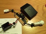
the m-stop is an inline configurable solid state modulator, I bought from the website and it costs about £38 and arrived in a few days, complete with English instructions the unit itself and a couple of resisters.
m-Stop brake light modulator - Brake Light Modulator m-Stop - Electrics
I had already installed a EL panel (see separate thread link below) and I wanted to tidy up the spliced connections at the same time (as it wasn't my finest work - although I am happy to report it's all still working 100% despite a bit of rain) so I decided to recycle the plug and wiring for this project and take off power for my EL panels from the same board.
http://www.motorcycle-talk.net/forum/mt-07-fz-07-modifications/820-el-panel-install-modification.html?highlight=panel
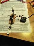
by the numbers;
1. measure and cut the board to size with the copper strips running parallel with the longest edge of the case.
2. mock the board to the case for size/fit, think about cable entry points and remember to use grommets if you are so inclined.
3. solder the yellow, blue and black supply wires to the copper tracks, making sure there is one connection per track only, give yourself space to work. YELLOW (12v+ brake), BLACK (0v Ground), BLUE (12v+ Side Light)
4. position the m-stop unit with the black lead connecting to the brake light on the PCB board.
5. solder into position making sure both wires of the m-stop are soldered to the same copper track (very important!) as the yellow wire.
6. break the copper track (remove copper) between the m-stop two solder points so power can only run through the m-stop.
7. solder the earth (BLACK) and 12v+ for the side light (BLUE) output wires to the board.
8. solder 1 x supplied resister between the 12v+ output from the m-stop and the ground
9. solder 3 x wires for the connection to the tail light to the same tracks as the supply.
10. if you want to take off power for lights (or in my case an EL panel transformer) then now you can make extra connections from the BLACK and BLUE wires or BLACK and YELLOW wires.
11. check continuity of all connections with a test meter. the yellow pathway will show some resistance (due to the m-stop unit), the black and blue pathways should show virtually no resistance.
12. set the dip switches to the pattern you want.
13. plug in and fire up the ignition.
14. once tested I used a little flexible glue to provide some extra mechanical fixing between PCB board and wires (personal preference)
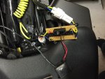
15. finally just need to drill casing for the cable grommets and put PCB in with a small piece of foam to prevent it rattling.
16. for MOT or run in with the old bill, it is very quick to unplug and the original loom can be restored in seconds.
finished product (almost!)
I have chosen the 8 rapid flashes followed by continuous brake light as this should get peoples attention! No change in the brightness of the brake light.
I will try and sort out a video once the install is finished off, old man nicked all my drill bits otherwise I think I would have had it final installed this evening!
any more questions ask away!
you will need all the usual kit for electronics i.e soldering iron, test meter, patience and a couple of hours as well as plug and some wire (for those wanting a removable solution) and a small case and a copper strip board from maplins (total about £8 for board and case)
the m-stop is an inline configurable solid state modulator, I bought from the website and it costs about £38 and arrived in a few days, complete with English instructions the unit itself and a couple of resisters.
m-Stop brake light modulator - Brake Light Modulator m-Stop - Electrics
I had already installed a EL panel (see separate thread link below) and I wanted to tidy up the spliced connections at the same time (as it wasn't my finest work - although I am happy to report it's all still working 100% despite a bit of rain) so I decided to recycle the plug and wiring for this project and take off power for my EL panels from the same board.
http://www.motorcycle-talk.net/forum/mt-07-fz-07-modifications/820-el-panel-install-modification.html?highlight=panel
by the numbers;
1. measure and cut the board to size with the copper strips running parallel with the longest edge of the case.
2. mock the board to the case for size/fit, think about cable entry points and remember to use grommets if you are so inclined.
3. solder the yellow, blue and black supply wires to the copper tracks, making sure there is one connection per track only, give yourself space to work. YELLOW (12v+ brake), BLACK (0v Ground), BLUE (12v+ Side Light)
4. position the m-stop unit with the black lead connecting to the brake light on the PCB board.
5. solder into position making sure both wires of the m-stop are soldered to the same copper track (very important!) as the yellow wire.
6. break the copper track (remove copper) between the m-stop two solder points so power can only run through the m-stop.
7. solder the earth (BLACK) and 12v+ for the side light (BLUE) output wires to the board.
8. solder 1 x supplied resister between the 12v+ output from the m-stop and the ground
9. solder 3 x wires for the connection to the tail light to the same tracks as the supply.
10. if you want to take off power for lights (or in my case an EL panel transformer) then now you can make extra connections from the BLACK and BLUE wires or BLACK and YELLOW wires.
11. check continuity of all connections with a test meter. the yellow pathway will show some resistance (due to the m-stop unit), the black and blue pathways should show virtually no resistance.
12. set the dip switches to the pattern you want.
13. plug in and fire up the ignition.
14. once tested I used a little flexible glue to provide some extra mechanical fixing between PCB board and wires (personal preference)
15. finally just need to drill casing for the cable grommets and put PCB in with a small piece of foam to prevent it rattling.
16. for MOT or run in with the old bill, it is very quick to unplug and the original loom can be restored in seconds.
finished product (almost!)
I have chosen the 8 rapid flashes followed by continuous brake light as this should get peoples attention! No change in the brightness of the brake light.
I will try and sort out a video once the install is finished off, old man nicked all my drill bits otherwise I think I would have had it final installed this evening!
any more questions ask away!
")